Here is the short history of the development steps leading up to the final installation
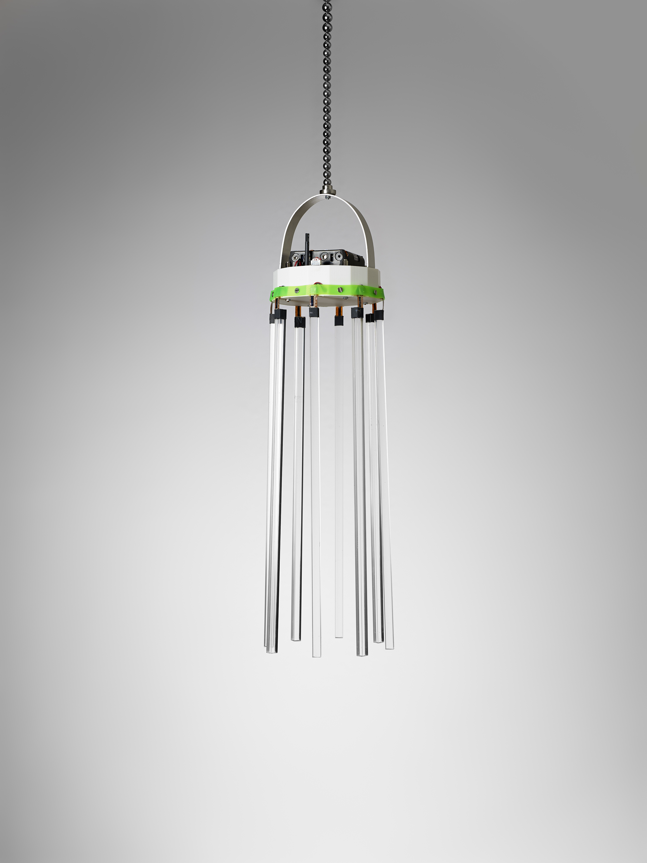
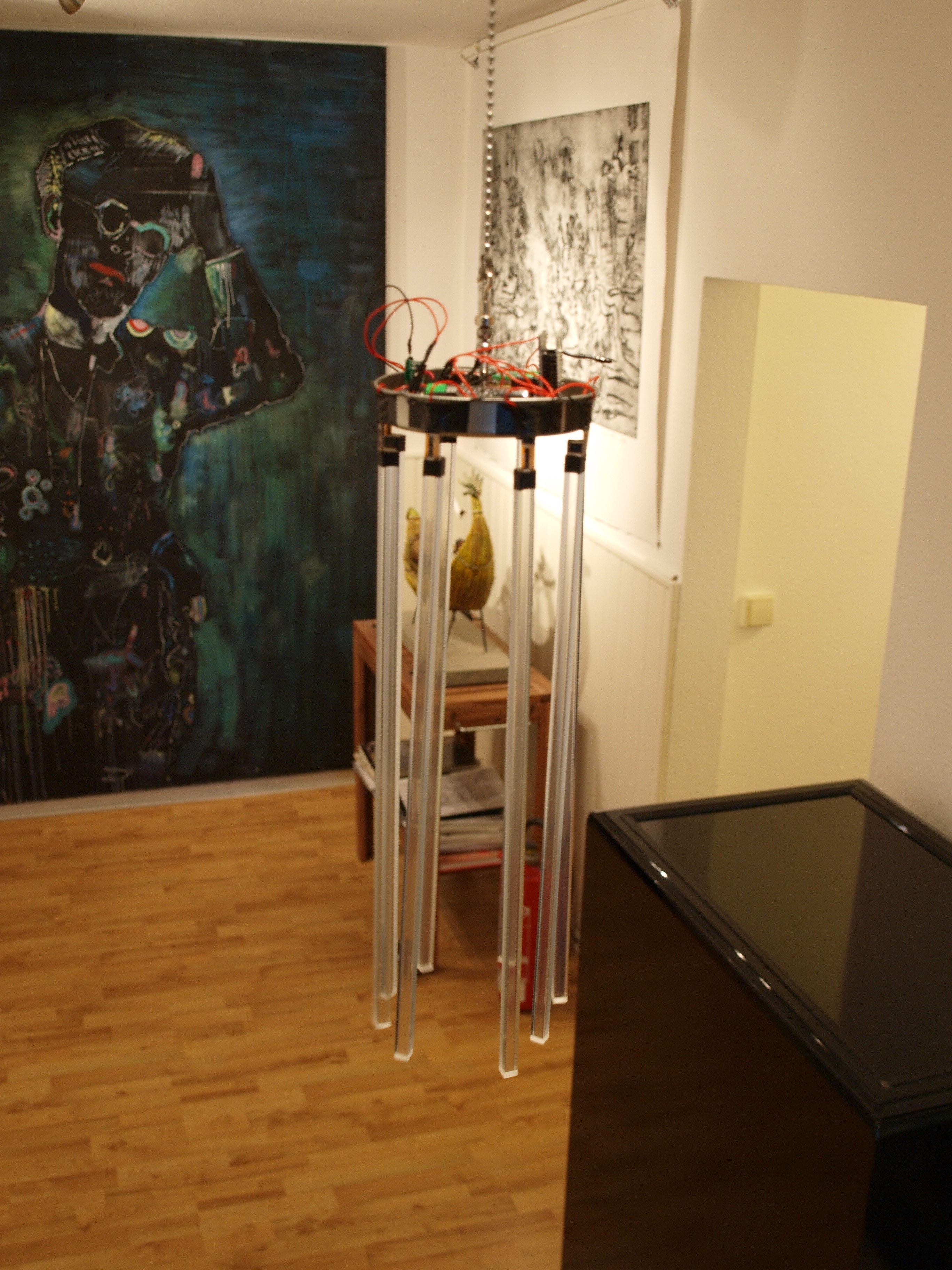
This is a photo of the first working version of the Modern Chimes:

Modern Chimes consists of a few functional units:
- A freely hanging electronic wind chime made of plexiglass, 8 Plexiglas tubes with embedded contact sensors without their own sound.
- A radio transmitting unit integrated in the wind chime for the contact signals to the receiving station.
- A wireless receiver unit with connected music sampler.
Video
Here is a video of the first screening as a wedding gift to my dear friends Claudius and Daniela without which I would never have built the wind chime because I wanted to create something unique for this occasion.
In the background I change the CF Cards again and again (described below) to load other sound scenarios.
… and now to the description of the individual components…
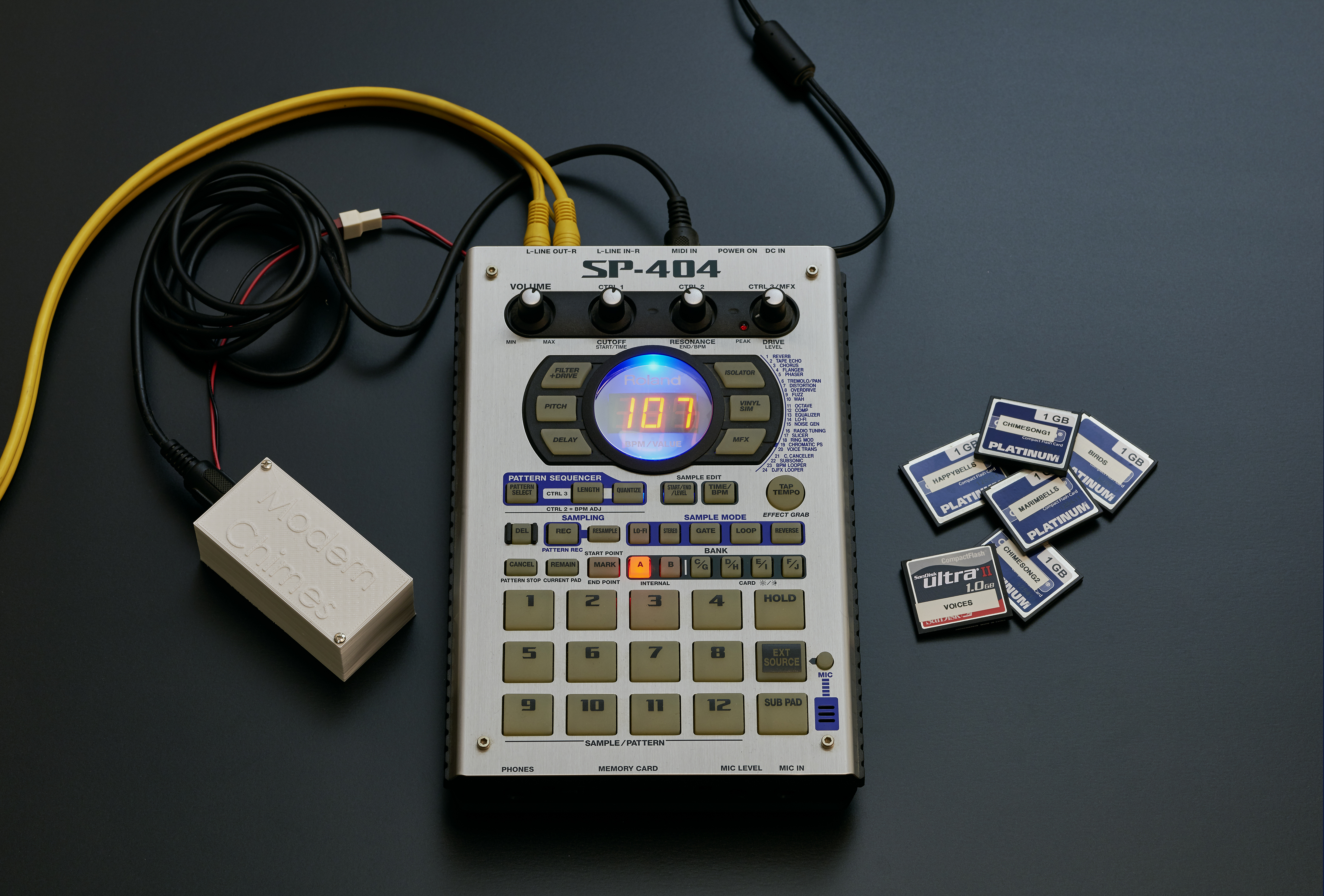
The music sampler
The ROLAND SH-404 music sampler is connected to the stereo. It can play up to 12 sounds simultaneously, the “Modern Chimes” wind chime broadcasts up to 8 sound events simultaneously.

The sounds (samples) are read into the music sampler via CompactFlash (CF) cards and can therefore be changed quickly.

Own samples can be done with free software (e.g. Audacity on PC) and transferred to the CF card (in root, i.e. at the top of the Roland folder) with a card adapter. The sounds can be MONO or stereo, AIFF or WAV, but always 44.1Khz and 16bit resolution. Stereo sounds consume more memory, but I haven’t reached the limit (even for one minute-long sounds). The CF cards must be pre-matted by the device once after purchase, see the SH-404 Manual. It’s going so fast that you think it didn’t work. If the sounds are on the map, they are read in alphabetical order by the SH-404 into the selected sound bank. (Sample for sample in specific pads, see the SH-404 Manual). This can take some time, but only once, because if you insert this card later, it will be recognized and the sounds will no longer have to be read in.
The music sampler supplies the external wireless receiver unit with power (9V DC) and is sensibly connected with an amplifier via cable. In case of poor grounding, a hum could arise but there is a grounding connection on the back of the SH-404.
 The 9V DC socket is supplied with electricity, while it should be noted that the Roland power supply unit leads +9V outside and GND inside, i.e. vice versa than most other power supplies.
The data comes in the MIDI standard via a MIDI 5pol DIN cable from the radio reception unit and contains note values. (Note ON) The volume is always the same and corresponds to the volume of the recorded sample. (Velocity 127). The note values are constant, i.e. each sensor tube sends exactly one (and always the same) note value when contacted.
The wind chime thus sends a note value per tube, which triggers the sample. The note value cannot be changed. The total of 8 note values are designed to control PAD 1-8 of the user soundbank C, namely note values 71 to 78. Each pad contains a different sampled sound and can be heard at the same time as everyone else.
Advanced users can copy sounds between the pads, as described in the manual. However, the sent note values are set in the firmware of the transmitting unit (Basic Stamp2) and are always 71 to 78.
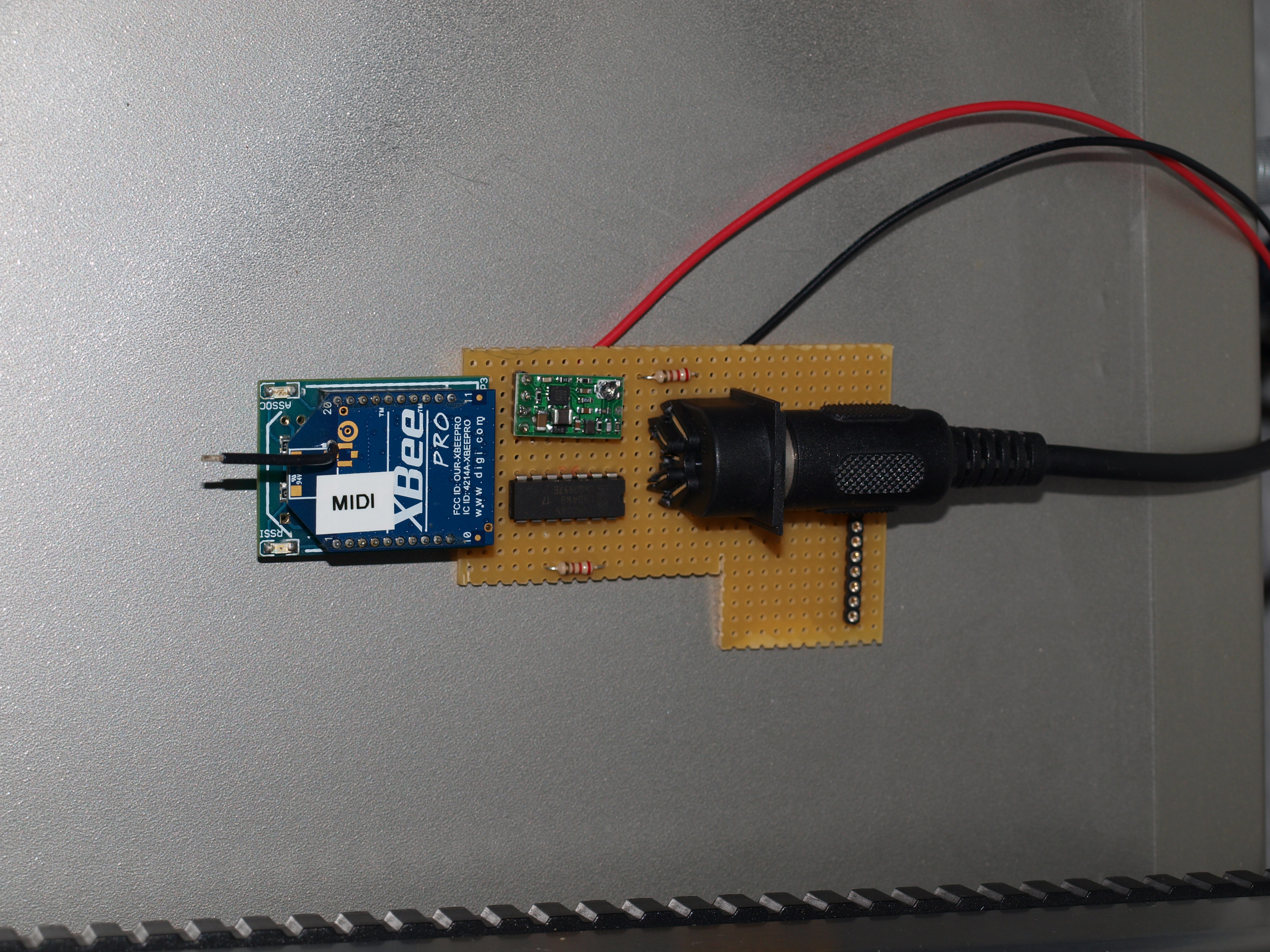
The radio reception unit:

It is a pure MIDI data receiver and is powered by the sampler with 9V. Thanks to an internal Step Up/Step Down voltage converter (Anyvolt Micro from Dimension Engineering), any voltage between 2.6V and 14V can be connected. The radio unit shows a constantly luminous red LED as soon as it is supplied with power. The radio unit contains XBee Pro radio module (applied on a Droids Simple Board) and extends about 1km in open terrain and through some walls in buildings. The XBee radio module has been set to the crooked baud rate of MIDI with a trick, see: http://www.ladyada.net/make/xbee/midibee.html .
The output is a standard 5-pole DIN MIDI cable (via a dual hex inverter) for connecting to the MIDI IN port of the SH-404
Here is a photo of the sampler with connected radio unit when receiving data from the sensor tubes 3,4,5,6

The sensor tubes
(still photographed here without GND cable on the silver bracket)

Modern Chimes contains 8 sensor tubes. Each of these Plexiglas tubes is equipped with a hall sensor at the lower end and generates a switching signal as soon as a magnetic field in sufficient thickness approaches about 5mm.

Each tube contains a hall sensor (Unipolar hall switch Conrad H501) and a 1K resistor. The resistance is between +5V and sensor output and generates a “high” level at the hall sensor so that the signal cannot flutter in the undefined state. (Since I later used this resistance on the microcontroller board you could also omit it in the tube, but it doesn’t hurt and you can’t get there anymore.
When the reverb sensor detects a magnetic field, it switches to LOW. The microcontroller acknowledges this with a short green LED flash.
Only the south pole of the magnet goes to switch the hall sensor, the north pole does not produce any effect.
The hall sensor is held in position with a hot deformed PVC rod in the tube
At the top of the tube a four-pole pin header is glued in, three pins are occupied:
GND (cable up to the other GND contacts) (not shown here in the photo)
+5V Input (ring cable with red plug-in jumpers)

Sensor OUT (cable to microcontroller)
All tubes are equipped with colour-arbitrary connectors, and no tubes always have GND contact and therefore all others too. This worked very well in the test runs. From one tube, the black encoded GND wire goes to the microcontroller.
At the output of the sensor is a approx. 30cm long cable soldered which ends in a pin plug which can then be plugged into the corresponding input of the processor. Everything is color coded (not black and red).
A red jumper cable is inserted on the bare free PIN (+5V), which supplies the tubes with +5V among themselves. The jumper cable in turn has a 30cm cable to supply power from the processor board.
The tubes are mounted on terminals via a silver wire bracket. This silver wire bracket can be bent for fine adjustments.
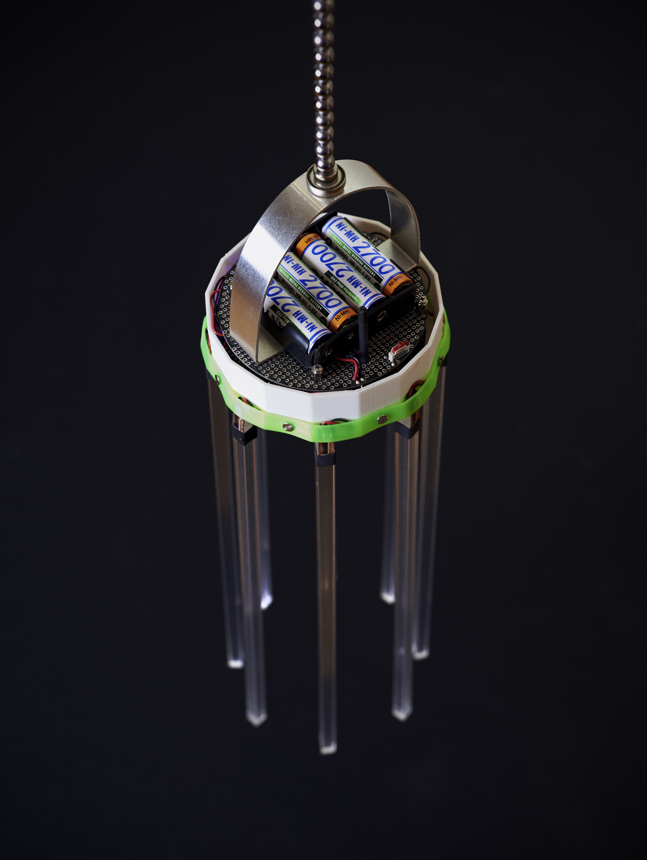
The battery housing
The battery housing is the lowest unit of the wind chhouse and thus the most accessible. The case can be opened counterclockwise by a screw movement, thereby better grip the upper lid and not on the neodymium magnets.
On the lid the neodymium quarder magnets (from Modulor) are glued on, actually you only need 8, I rather have double as many (i.e. 16 pieces) glued on, which is not easy because first of all the right side to the reverberation sensor has to show and the neighboring magnets like the Magnets. The attachment to the lid ensures optimal alignment to the reverberation sensor, as the lid is always in the same position to the sensor tubes (and if not it can be brought into them by gentle rotation)
For easier change of batteries/batteries, the lower half of the case with the batteries can be completely disconnected from the wind chime by means of a plug-in connection. A built-in Step UP DC-DC converter (LV Boost from Dimension Engineering) is set to 5V and converts any input voltage from 0.5V to 5V to 5V constant. At 1.5A, the output power is well above demand and therefore no component is warm. Both AA batteries (3*1.2V = 3.6V) and AA batteries (3*1.5V = 4.5V) can be used.

The batteries themselves are housed in a modified battery housing (reduced from 4*AA to 3*AA and rounded). The reduction and rounding is necessary so that the power supply fits into the plastic housing (unfortunately not from Modulor, only to get from the wholesaler as a pattern) The correct polarity and fixed seat must be taken into account. Always release the batteries from the PLUS side, otherwise the minus springs can bend. Of course, axing on the right pole and preferring to leave time and look twice. Three charged 2700mAh batteries last about half a day, batteries probably last longer but their use makes no ecological sense.
As soon as the power plug is plugged in, the red LED of the wireless module flashes and the green LED flashes briefly when magnetic field contact.
When re-screwing the lower part of the battery housing, please make sure that the housing is not screwed in an edge (slanted).
The processor board
The wind chime is powered by batteries because an external power supply would limit the flexibility in the location selection for the installation in the wind.
The processor was programmed on a bread board and the circuit tested. Then the actual processor board could be manufactured and the processor was plugged in there
The processor board consists of a Basic Stamp2 (I also tested the Basic Stamp2sx but it does not bring any advantage) and an XBee Pro Wireless wireless module (applied on a Droids Simple Board). The radio module has a range of one kilometer in open terrain.
The processor board is a round ground hole grid board in the size of the plastic box (which unfortunately could not be obtained from Modulor but only as a sample from the wholesaler) into which it is fitted.

At the inputs PO to P7 from the Basic Stamp2 pin jacks for the sensors are soldered and a 10K resistor to +5V to set the input to HIGH. on pin 24 is supplied +5V and provided for the sensors, on pin 23 GND.
Pin 13 controls an LED that is switched over 220 ohms against +5V, i.e. for lighting, the PIN switches to LOW.
The serial output of the Basic Stamp2 is on PIN 20 and goes via a 220 Ohm resistor into the RX input of the XBee Pro module. For simplicity, this module is plugged into a Droids Simple Board that controls the 3.3V power supply, has LEDs and PINS at the right hole grid spacing. GND and +5V are fed to this simple board.
The XBee Pro module has been set to MIDI Baudrate, actually this is not possible but thanks to this hint: http://www.ladyada.net/make/xbee/midibee.html
The BasicStamp2 queries the sensor inputs in an infinite loop. If it detects a LOW (hall sensor has switched) at an input, then the green LED flashes briefly and a midi note specific to this sensor (note value 71 to 78 depending on the sensor tube) is sent to the serial output which the radio module sends immediately. A depressing software module ensures that a note that sounds once can not be struck too quickly.
At the bottom of the processor (as mentioned PIN 24 and PIN 23) is a plug cable soldered through the plastic housing into the battery housing and thus feeds the power.
A note on transport and suspension:
The neodymium magnets are enormously strong despite their small dimensions. If you pass a steel rack or steel rod, it pulls all magnets off the housing cover despite super glue, so always very carefully and far away from metallic objects transport and hang.
For an almost smooth constriction, the upper suspension is a neodymium magnetic ball, therefore it is best to use a counter magnet or a chain for suspension. Always secure the suspension with the nylon safety cord, as the filigree object is safely damaged in the event of a crash, no iPhone is…
MODERN CHIMES V2
Modern Chimes V2 doesn’t mean this is an “improved” version, it’s just different.
Version 1 had a special sensitivity in handling, transport and handling. This was due to the neodymium magnets and their extraordinary power.
I wanted to bypass this in the new version and therefore used a completely different kind of sensor technology. This makes the setup much easier, transports are no longer critical.
Furthermore, version 1 had the disadvantage that for the generation of a music event the same force was always needed by the wind and therefore the chime was not adjustable for different wind strengths. I also changed this to version 2, version 2 now has a switch for a two-step sensitivity.
Version 2 can also be programmed without having to take out the BasicStamp and has an on/off switch. Version 2 no longer uses 4 but only 2 batteries and therefore has only half the running time.
Compared to version 1, the original version, this new version behaves differently, I also did not want to create a copy, but rather to provoke other experiences and interactions.
Here are all the changes tabular:
- Programming plug for programming without disassembly
- No reverb sensors and neodymium magnets, now bending sensors in the tube suspension
- Programmable sensitivity, switchable in two stages
- Waiting breaks per sensor for less nervous music generation in strong winds
- two instead of four batteries
- All on a board on the upper platform, middle rod completely eliminated
- Square acrylic rods instead of round acrylic tubes
- New due to bending sensors: Auto-calibration after switching on
I still use a Basic Stamp SX, even though I have regretted it many times because the low variable space and very limited language range complicates the programming work considerably. In the next version, I would like to use a different processor to perform much more complex sensor evaluations.
There are no changes to the sampler and its Midi radio receiver unit, only for the Chime and its processor board.
MODERN CHIMES V3
My favorite project “Modern Chimes” doesn’t leave me mentally alone. Now it’s 2013 and I’m ready for the new version.
Why a new version again? I noticed during version 2 screenings that the result was impressive, but not as I originally wanted. It was good and I should have left it that way. Wouldn’t there be a part of the idea of John Cage in me who wants and needs chance, but within a controlled or planned environment.
In order to get more control over the function of the wind chime, I definitely had to change the processor. That’s why I switched to Arduino for the first time, in my case an Arduino Micro. Programming the Arduino is super easy for me, because I have taught myself really hardcore programming in C and C++ during the development of the data gloves and here in the wind chime much less time-critical processes take place. I then made the code even more energy efficient and now Come with a sentence (4 pcs. 2950mAh Mignon) of charged batteries 12 hours wide, i.e. the wind chime can work all day long without further action.
Furthermore, I now have a UP!plus 3D printer and wanted to design and print the case of the wind chime myself. This was particularly difficult, because despite years of 3D modelling experience from the days of my companies Fourth Art GmbH and noDNA AG, I no longer had any tools with which I could (legally) construct sensibly. After months of trying, I finally did it with Google Sketch and went through many hells.
Also the wireless midi note receiver, which I had built as an addition to the sampler had to get a housing and this is now 3D printed, which was quite simple.
From the experience of V2, I wanted to keep the hanging sensor tubes under preload in V3, i.e. the bending sensors do not hang straight downwards, but slightly obliquely. Thus, they are already curved in the wind still and this ensures more stable values.
Furthermore, there is now a rotary knob that can adjust the sensitivity of the wind chime. Counterclockwise, it becomes more sensitive, clockwise less sensitive and therefore less nervous with stronger winds. Therefore, the previous switch of two-stage sensitivity is omitted. This is now internally divided into 11 levels. The controller is read in once after switching on, i.e. must be switched off/on when changing.
In addition, it has been the case that every battered tone (or each triggered sample) was the same, exactly in the recorded volume. That is no longer the case. The volume is now selected by a random process from four volumes. This brings more dynamism and variation.
For a certain amount of time per sensor, the repetition of an event is suppressed, up to about 70 seconds, i.e. the samples should not be repeated constantly if the wind is uniform and the wind chime does not rotate in the wind.